August 24th, 2013 | categorizilation: all categories,equipment,Post-2008
Get in and support an awesome product for keeping people who longboard for transport clean and dry – Wheel Shields:В http://www.kickstarter.com/projects/1522548247/wheel-shields-longboarding-technology
————————–
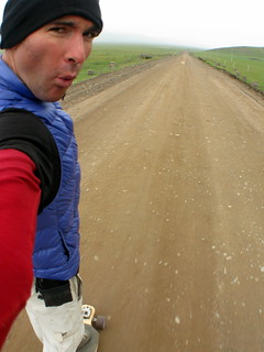
Way back in 2008, I was in western China sitting in a stifling internet cafe. I had already skated over 6,000 miles (9,600km) across the US and Europe, but in the previous days,В I had spent a couple of days skating on wet roads, getting legs covered in road grime, yak shit, and slug guts. Some of the roads were also hard-packed dirt, which were still skateable when they were wet, but caused havoc on my shoes and clothes. This was a super frustrating issue. Sure, dirty pants and dripping wet shoes can be cool. But not when you want to sit down at a restaurant, cafe, internet cafe, someone’s chair in their house, etc.
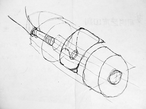
Sitting in that internet cafe, I thought up an idea for a fender/mudguard setup for a longboard. Below is the sketch I did in 2008, to explain the idea to my product-designer brother. “Can it be done?” I asked. He was confident that it could be done, but it would require a lot of work prototyping before a decent device could be created.В The idea promptly got put in the too-hard-basket.
Fast forward to 2012. I get an email out of the blue fromВ Chase Kaczmarek from the US, asking for my opinion about his invention called Wheel Shields. He was developing them into a marketable product. I said that they are brilliant. A year later, he’s got a very elegant, refined product ready to produce. The one thing he’s not got is money to create the tooling to mass produce them. That’s where his Kickstarter Campaign comes in:В http://www.kickstarter.com/projects/1522548247/wheel-shields-longboarding-technology.
He needs US$25,000. He’s raised just over US$14,000 so far, with 11 days left in his fund-raising campaign. I’ve already pledged my support by ordering a set. I really want to get my set of Wheel Shields. It will mean that skating to school and work will be a reliable option, without having to worry about rain during the day creating wet roads. So do get in there and support a great idea and the masses of work that has gone into making them work:В http://www.kickstarter.com/projects/1522548247/wheel-shields-longboarding-technology.
To be honest, I think for purely distance skaters, who are not concerned with wheelbite or ‘shoe-bite’ or stand-on-wheels-tricks, they are a little bit on the over-engineered side. For just ‘fender’ or mudguard applications, light plastic would be fine. But still,В I do stand by my words:В Wheel Shields are brilliant. Hands down the biggest innovation in longboarding in a long time. I wish I had Wheel Shields when I skated across the US, Europe and China. Wheel Shields have changed the longboard transportation paradigm forever. They are an elegant solution to a frustrating problem.
* The quote above was edited slightly on Chase’s Kickstarter page to keep things brief.
** I should also mention that I am in no way officially associated with Wheel Shields, or receiving compensation from them…
August 9th, 2013 | categorizilation: all categories,Hokkaido (Japan),Post-2008,Sapporo,Technology
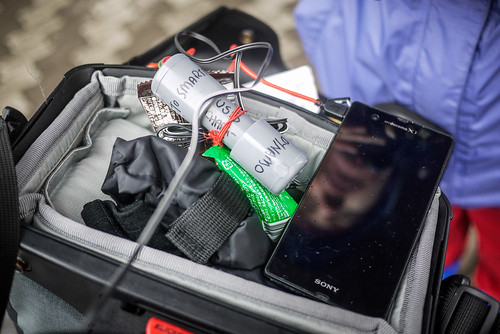
Following on from my previous post describing how to make a home-made DIY bicycle dynamo-hub USB charger, I have updated the old PVC-pipe container version (at the end of the last post). I removed the innards and transferred them to something more interesting: a clear acrylic pipe, with corks in the ends.
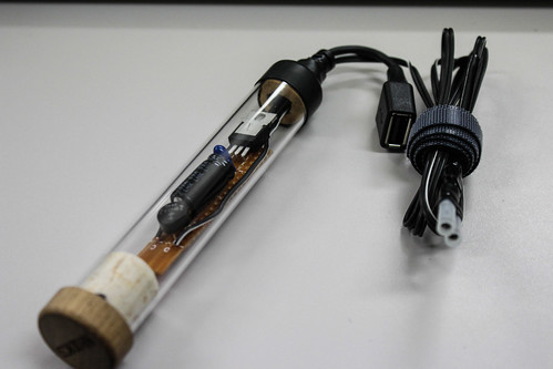
As you can see, I have also replaced the micro-USB plug with a female USB-A socket, so that I can plug any USB-type cord into it (micro-USB, mini-USB, iPhone-charger-USB, etc). This particular version is not particularly weather-tight. The actual size of it is larger than the previous shrink-wrapped version also. But it is certainly smaller than the PVC-pipe version, and should serve me well.
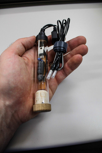
Haidee and I are heading off on a two-week cycle tour starting in a couple of days, so both chargers will get a thorough testing ![]()
August 6th, 2013 | categorizilation: all categories,equipment,Hokkaido (Japan),Japan,Post-2008
жң¬жҠ•зЁҝгҒ§гҒҜгҖҒгғҸгғ–гғҖгӮӨгғҠгғўжҗӯијүгҒ®иҮӘи»ўи»ҠгҒ«дҪҝгҒҲгӮӢгҖҒгӮ№гғһгғјгғҲгғӣгғіз”ЁгҒ®USBе……йӣ»еҷЁгҒ®дҪңгӮҠж–№гӮ’зҙ№д»ӢгҒ—гҒҫгҒҷгҖӮгӮўгӮӨгғҮгӮЈгӮўиҮӘдҪ“гҒҜMr. Howdy, В Arenddeboer.comгҒЁPeterгҒӢгӮүжқҘгҒҰгҒ„гҒҫгҒҷгҒҢгҖҒеҪјгӮүгҒ®гӮӨгғігӮ№гғҲгғ©гӮҜгӮ·гғ§гғігҒ§гҒҜгҖҒеӣһи·ҜеӣігҒҢгҒӮгӮӢзЁӢеәҰиӘӯгӮҒгҒӘгҒ„гҒЁгғҜгӮұгҒҢгҒӨгҒӢгҒҝгҒ«гҒҸгҒ„гҒ§гҒҷгҖӮз§ҒиҮӘиә«гҒҜеӣһи·ҜеӣігҒҢиӘӯгӮҒгҒӘгҒ„гҒ®гҒ§гҖҒеҗҢгҒҳгӮҲгҒҶгҒ«еӣһи·ҜгҒҢиӘӯгӮҒгҒӘгҒ„дәәй–“гҒ®гҒҹгӮҒгҒ«гҒ§гҒҚгӮӢгҒ гҒ‘з°ЎеҚҳгҒ«гҒ“гҒ“гҒ§иӘ¬жҳҺгҒ—гҒҫгҒҷгҖӮ
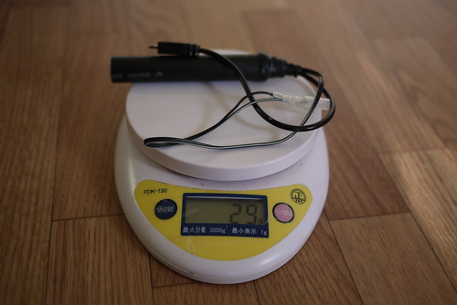
з§ҒгҒҢдҪңгҒЈгҒҹгғҖгӮӨгғҠгғўгғҸгғ–з”ЁгӮ№гғһгғјгғҲгғӣгғіе……йӣ»еҷЁпјҲи»ҪгҒ•пјҡ29gпјү
д»ҠеӣһдҪңгӮӢе……йӣ»еҷЁгҒ®жҰӮиҰҒ
з·ҸиІ»з”Ёпјҡ1,500еҶҶзЁӢеәҰпјҲйғЁе“ҒгҒ®гҒҝгҒ§гҖҒеҚҠз”°гҒ”гҒҰгҒӘгҒ©гҒ®еҝ…иҰҒгҒӘе·Ҙе…·гҒҜеҗ«гҒҫгҒӘгҒ„пјү
йҮҚгҒ•пјҡ29g
иҖҗеҖҷжҖ§пјҡжңүгӮҠ
еҮәеҠӣпјҡ5V 1A DC (USBжЁҷжә–пјү
е…ҘеҠӣпјҡ6V AC (гҒ»гҒЁгӮ“гҒ©гҒ®иҮӘи»ўи»ҠгғҸгғ–гғҖгӮӨгғҠгғўгҒҜгҒ“гӮҢгҒ«гҒӮгҒҹгӮӢпјү
е……йӣ»еҠ№зҺҮпјҡгӮҪгғӢгғјExperia ZпјҲгӮҸгӮҠгҒЁгғҗгғғгғҶгғӘгғје®№йҮҸгҒ®еӨҡгҒ„пјҲ2330mAhпјүгӮ№гғһгғјгғҲгғӣгғіпјүгӮ’гҖҒиө°гӮӢ1kmгҒ”гҒЁгҒ«1пј…е……йӣ»гҒ—гҒҰгҒ„гҒҸпјҲгӮ№гғһгғӣгғігҒ®йӣ»жәҗгҒҢOFFгҒ®зҠ¶ж…Ӣпјү
е……йӣ»й–Ӣе§ӢжҷӮйҖҹпјҡ5.5km/h
е……йӣ»еҷЁгҒ®гҖҢеҪ№еүІгҖҚ
гғ‘гӮҪгӮігғігӮ„гӮігғігӮ»гғігғҲгҒ§гӮ№гғһгғӣгғігӮ’е……йӣ»гҒҷгӮӢгҒЁгҒҚгҒ«гҖҒгӮ№гғһгғӣгғігҒ«жөҒгӮҢгҒҰгҒҸгӮӢйӣ»еҠӣгҒҜзӣҙжөҒпјҲDCпјүгҒ§йӣ»ең§гҒҜ5VгҒЁгҒӘгҒЈгҒҰгҒ„гҒҫгҒҷгҖӮгҒ“гӮҢгҒҜUSBжЁҷжә–гҒ®йӣ»ең§гҒ§гҒҷгҖӮгҒ—гҒӢгҒ—гҖҒиҮӘи»ўи»ҠгҒ®гғҸгғ–гғҖгӮӨгғҠгғўгҒҢеҮәеҠӣгҒҷгӮӢйӣ»еҠӣгҒҜдәӨжөҒпјҲACпјүгҒ§6VгҒ§гҒҷгҖӮ гҒқгҒ®гҒҫгҒҫгӮ№гғһгғӣгғігҒ®е……йӣ»гҒ«дҪҝгҒҲгҒӘгҒ„гӮҸгҒ‘гҒ§гҒҷгҖӮгӮҲгҒЈгҒҰгҖҒгғҖгӮӨгғҠгғўгғҸгғ–гҒ®6VпјҲACпјүгӮ’гҖҒгғ‘гӮҪгӮігғігҒӘгҒ©гҒ®USBгҒӢгӮүеҮәеҠӣгҒ•гӮҢгӮӢйӣ»еҠӣгҒЁеҗҢж§ҳгҒ®йӣ»еҠӣпјҲ5VпјҲDCпјүпјүгҒ«еӨүжҸӣгҒ•гҒӣгӮӢеҝ…иҰҒгҒҢгҒӮгӮҠгҒҫгҒҷгҖӮгҒ“гҒ®е……йӣ»еҷЁгҒҢгҒқгҒ®еҪ№зӣ®гӮ’жһңгҒҹгҒ—гҒҫгҒҷгҖӮ
жіЁж„Ҹпјҡз§ҒгҒҜгҒ»гӮ“гҒ®е°‘гҒ—гҒ—гҒӢгҖҒйӣ»еӯҗе·ҘдҪңгҒ«й–ўгҒҷгӮӢзҹҘиӯҳгҒҜгҒӮгӮҠгҒҫгҒӣгӮ“гҖӮжң¬е……йӣ»еҷЁгӮ’д»ҠгҒҫгҒ§1,000kmгҒ»гҒ©гҒ®иҮӘи»ўи»Ҡгғ„гғјгғӘгғігӮ°гҒ§дҪҝгҒ„з¶ҡгҒ‘гҒҰгҒ„гҒҰе•ҸйЎҢгҒҜе…ЁгҒҸгҒӘгҒӢгҒЈгҒҹгҒ®гҒ§гҒҷгҒҢгҖҒиҰӢйҖғгҒ—гҒҰгҒ„гӮӢгҒЁгҒ“гӮҚгҒҢгҒӮгӮӢгҒӢгӮӮгҒ—гӮҢгҒҫгҒӣгӮ“гҖӮгҒқгҒ®гҒҹгӮҒгҖҒгҒ“гҒ®е……йӣ»еҷЁгӮ’дҪҝгҒҶгҒ“гҒЁгҒ«гӮҲгҒЈгҒҰгҒӮгҒӘгҒҹгҒҢеӨ§дәӢгҒ«гҒ—гҒҰгҒ„гӮӢйӣ»еӯҗж©ҹеҷЁгҒҢеЈҠгҒ•гӮҢгҒҰгҒ—гҒҫгҒҶеҸҜиғҪжҖ§гҒҢгӮјгғӯгҒЁгҒҜиЁҖгҒ„еҲҮгӮҢгҒҫгҒӣгӮ“гҖӮжң¬е……йӣ»еҷЁгҒ®гҒ”дҪҝз”ЁгҒҜиҮӘе·ұиІ¬д»»гҒ§гҒҠйЎҳгҒ„гҒ—гҒҫгҒҷгҖӮиҮӘе·ұгҒ§иІ¬д»»гӮ’иІ гҒҶгҒ®гҒҜе«ҢгҒ гҒЁгҒ„гҒҶж–№гҒҜгҒ“гӮҢгӮүгҒ®еёӮиІ©иҮӘи»ўи»Ҡз”ЁUSBе……йӣ»еҷЁгҒ®гҒ”иіје…ҘгӮ’гҒҠеӢ§гӮҒгҒ—гҒҫгҒҷпјҡBright Light RevolutionпјҲйқһеёёгҒ«ж је®үгҒ гҒЁжҖқгҒ„гҒҫгҒҷпјүгҖҒBusch+Muller Luxos IQ2гҖҒToutTerrain Plug IIгҖӮ
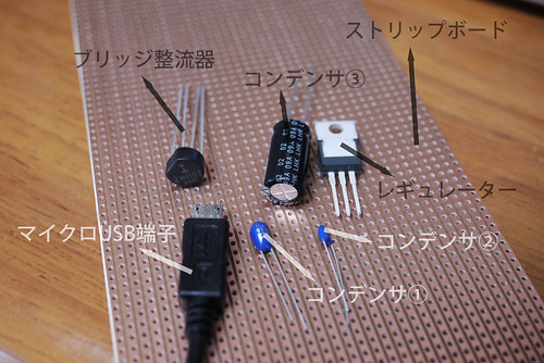
з”Ёж„ҸгҒҷгӮӢгҒӘйғЁе“ҒпјҲжңӯе№ҢеёӮеҶ…гҒҜгҖҒгӮ№гғҲгғӘгғғгғ—гғңгғјгғүд»ҘеӨ–гҒ«гҒҜгҒҷгҒ№гҒҰжў…жҫӨз„Ўз·ҡйӣ»ж©ҹгҒӢгӮүе…ҘжүӢеҸҜиғҪпјү
гӮ№гғҶгғғгғ—пј‘
гӮ№гғҲгғӘгғғгғ—гғңгғјгғүгӮ’4з©ҙв…№25з©ҙгҒ§й•·зҙ°гҒҸеҲҮгӮҠгҒҫгҒҷгҖӮеҲҮгӮҠж–№гҒҜгҖҒгӮ«гғғгӮҝгғјгҒ§дёЎйқўгҒ«еҲҮгӮҠзӣ®гӮ’еј•гҒ„гҒҰгҖҒеүІгӮҠгҒҫгҒҷгҖӮ
гӮ№гғҶгғғгғ—пј’
з”Ёж„ҸгҒ—гҒҹпј”пҪҳпј’пј•гҒ®еҹәжқҝгҒ«йғЁе“ҒгӮ’дёҰгҒ№гҒҰгҒ„гҒҚгҒҫгҒҷгҖӮгӮігғігғҮгғігӮөгҒ®и¶ігҒҜгҖҒй•·гҒ„гҒ»гҒҶгҒҢйҷҪпјҲпјӢпјүгҖҒзҹӯгҒ„гҒ»гҒҶгҒҢйҷ°пјҲпјҚпјүгҖӮеҶҷзңҹгӮ’гӮҜгғӘгғғгӮҜгҒҷгӮӢгҒЁжӢЎеӨ§гҒ•гӮҢгҒҫгҒҷгҖӮ

гӮ№гғҶгғғгғ—пј“
гғ–гғӘгғғгӮёж•ҙжөҒеҷЁгӮ’иЁӯзҪ®гҒҷгӮӢгҖӮгҒ“гҒ®гӮ№гғҶгғғгғ—гҒ«гҒҠгҒ„гҒҰгӮӮгҖҒеҲҶжҘөпјҲпјӢгҒЁвҖ•гҒ®дҪҚзҪ®пјүгӮ’жіЁгҒ—гҒҰиЁӯзҪ®гҒ—гҒҫгҒ—гӮҮгҒҶгҖӮ
гҒқгҒҶгҒҷгӮӢгҒЁд»ҠгҒ®ж®өйҡҺгҒ§гҒҜдёҠгҒӢгӮүиҰӢгӮӢгҒЁд»ҘдёӢгҒ®гӮҲгҒҶгҒ«иҰӢгҒҲгҒҰгҒ„гӮӢгҒҜгҒҡгҒ§гҒҷгҖӮ
гҒ“гҒ®гӮҲгҒҶгҒ«гҒӘгҒЈгҒҰгҒ„гӮӢгҒ®гҒ§гҒӮгӮҢгҒ°гҖҒж¬ЎгҒ«йғЁе“ҒгӮ’еҚҠз”°д»ҳгҒ‘гҒ—гҒҰеӣәе®ҡгҒ—гҒҰиЎҢгҒҚгҒҫгҒҷгҖӮйғЁе“ҒгҒ®йҒҺзҶұгҒ«жіЁж„ҸгҒҷгӮӢгҒЁгҒЁгӮӮгҒ«гҖҒдёҰеҲ—гҒ«гҒӘгҒЈгҒҰгҒ„гӮӢгғЎгғғгӮӯгӮ’жЁӘж–ӯзҡ„гҒ«еҚҠз”°гҒҢжөҒгӮҢгҒӘгҒ„гӮҲгҒҶгҒ«жіЁж„ҸгҒ—гҒҫгҒҷгҖӮ
гҒқгҒҶгҒҷгӮӢгҒЁд»ҘдёӢгҒ®гӮҲгҒҶгҒ«иҰӢгҒҲгӮӢгҒҜгҒҡгҒ§гҒҷгҖӮгғЎгғғгӮӯгҒҢеүҠгӮүгӮҢгҒҰгҒ„гӮӢз®ҮжүҖгҒҢгҒ„гҒҸгҒӨгҒӢгҒӮгӮҠгҒҫгҒҷгҒҢгҖҒдёӢгҒ®ж–№гҒ®з®ҮжүҖгҒ®гҒҝгғЎгғғгӮӯгӮ’еүҠгӮҠгҒҫгҒҷпјҲе…ҘеҠӣйӣ»ж°—гҒҢзӣҙжҺҘгғ¬гӮ®гғҘгғ¬гғјгӮҝгғјгҒ«жөҒгӮҢгҒӘгҒ„гӮҲгҒҶгҒ«йҳІгҒҗгҒҹгӮҒгҒ«еүҠгӮҠгҒҫгҒҷпјүгҖӮеҶҷзңҹгҒ«еҶҷгҒЈгҒҰгҒ„гӮӢд»–гҒ®з®ҮжүҖгҒҜз„ЎиҰ–гҒ—гҒҰгӮӮOKгҒ§гҒҷгҖӮ5mmгҒ®гғүгғӘгғ«гҒ§жүӢеӣһгҒ—гҒ§еүҠгӮӢгҒ“гҒЁгҒҢгҒ§гҒҚгҒҫгҒҷпјүгҖӮ

гӮ№гғҶгғғгғ—пј”
гғһгӮӨгӮҜгғӯUSBз«ҜеӯҗгӮ’жә–еӮҷгҒ—гҒҫгҒҷгҖӮUSBвҶ’гғһгӮӨгӮҜгғӯUSBгӮұгғјгғ–гғ«гӮ’еҲҮгӮҠгҒҫгҒҷгҖӮUSBгҒ®еӨ§гҒҚгҒ„ж–№гҒҜдёҚиҰҒгҒ§гҒҷгҖӮUSBгӮұгғјгғ–гғ«гҒ®еҶ…еҒҙгҒҜгҒҹгҒ„гҒҰгҒ„гҒ®е ҙеҗҲгҒҜй»’пјҲпјҚпјүгҖҒиөӨпјҲпјӢпјүгҖҒзҷҪпјҲгғҮгғјгӮҝпјүгҒЁгҒӘгҒЈгҒҰгҒ„гҒҫгҒҷгҖӮд»ҠеӣһгҒҜгғҮгғјгӮҝгҒҜиҰҒгӮүгҒӘгҒ„гҒ®гҒ§гҖҒзҹӯгҒҸеҲҮгҒЈгҒЎгӮғгҒ„гҒҫгҒҷгҖӮжҷӮгҒ«гҒҜйҷ°гҒ®ж–№гҒҜгӮ°гғӘгғјгғіиүІгҒ«гҒӘгҒЈгҒҰгҒ„гӮӢе ҙеҗҲгҒҢгҒӮгӮҠгҒҫгҒҷгҖӮ

гӮ№гғҶгғғгғ—пј•
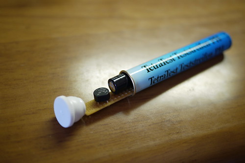
гғһгӮӨгӮҜгғӯUSBгӮұгғјгғ–гғ«гӮ’еҹәжқҝгҒ«еӣәе®ҡгҒҷгӮӢеүҚгҒ«гҖҒйҒ©еҲҮгҒӘе®№еҷЁгӮ’жҺўгҒ—гҒҫгҒ—гӮҮгҒҶгҖӮгғӣгғјгғ гӮ»гғігӮҝгғјгҒ«иЎҢгҒЈгҒҰгӮҰгғӯгӮҰгғӯгҒ—гҒҰжҺўгҒҷгҒ®гӮӮгӮўгғӘгҒ§гҒҷгҒҢгҖҒд»ҠеӣһгҒ®еҹәжқҝгӮ’гҒҚгӮҢгҒ„гҒ«еҸҺзҙҚгҒҷгӮӢгҒ®гҒҜгғӣгғјгғ гӮ»гғігӮҝгғјпјҲгғ“гғҗгғӣгғјгғ пјүгҒ§иҰӢгҒӨгҒ‘гҒҹгҖҢгғҶгғҲгғ© гғҶгӮ№гғҲи©ҰйЁ“зҙҷ pHгҖҚгҒ®зј¶гҒ§гҒҷгҖӮеҗҢгҒҳгӮҲгҒҶгҒӘеҜёжі•гҒ®гӮўгғ«гғҹгғ‘гӮӨгғ—гҒ§гӮӮжңүгӮҠгҒ§гҒ—гӮҮгҒҶгҖӮгғҶгғҲгғ©гҒ®зј¶гӮ’дҪҝгҒҶе ҙеҗҲгҖҒгӮЁгғігғүгӮӯгғЈгғғгғ—гҒ«з©ҙгӮ’гҒӮгҒ‘гҒҰгӮұгғјгғ–гғ«гҒІгҒӯгӮҠйҳІжӯўгҒ®гӮ°гғӯгғЎгғғгҒЁгӮ’е…ҘгӮҢгӮӢгҒЁгӮҸгӮҠгҒЁгҒҚгӮҢгҒ„гҒ«еҮәжқҘдёҠгҒҢгӮҠгҒҫгҒҷгҖӮ
гӮ№гғҶгғғгғ—пј–
гғҸгғ–гғҖгӮӨгғҠгғўгҒ«жҺҘз¶ҡгҒҷгӮӢгӮұгғјгғ–гғ«гҒЁгӮ№гғһгғӣгғігҒ«жҺҘз¶ҡгҒҷгӮӢгғһгӮӨгӮҜгғӯUSBгӮұгғјгғ–гғ«гӮ’е®№еҷЁгҒ®з©ҙгҒ«е…ҘгӮҢгҖҒеҹәжқҝгҒ«еӣәе®ҡгҒ—гҒҫгҒҷгҖӮгҒҫгҒҡгҒҜгғһгӮӨгӮҜгғӯUSBгӮұгғјгғ–гғ«гҒ®ж–№гҒ§гҒҷгҖӮгҒ“гҒ“гҒ§гҒ®еҲҶжҘөгҒҢеӨ§дәӢгҒ§гҒҷпјҒиөӨз·ҡгҒҢпјӢгҒ®еҲ—гҒ«гҖҒй»’гҒҢвҖ•гҒ®еҲ—гҒ«еӣәе®ҡгҒ—гҒҫгҒҷгҖӮ
 гҖҖ
гҖҖ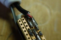
ж¬ЎгҒ«гҖҒгғҖгӮӨгғҠгғўгғҸгғ–гҒ«жҺҘз¶ҡгҒҷгӮӢгӮұгғјгғ–гғ«гӮ’д»ҳгҒ‘гҒҫгҒҷгҖӮгҒ“гҒ“гҒ§гҒ®еҲҶжҘөгҒҜй–ўдҝӮгҒӘгҒ„гҒ§гҒҷгҖӮгғ–гғӘгғғгӮёж•ҙжөҒеҷЁгҒЎгӮғгӮ“гҒҢгҒЎгӮғгӮ“гҒЁж•ҙзҗҶгҒ—гҒҰгҒҸгӮҢгҒҫгҒҷгҖӮ
гӮ№гғҶгғғгғ—пј—
гӮ№гғҶгғғгғ—пј•гҒ§иҰӢгҒӨгҒ‘гҒҹе®№еҷЁгҒ«еҹәжқҝгӮ’иЁӯзҪ®гҒ—гҒҫгҒҷгҖӮиҖҗеҖҷжҖ§гӮ’еҗ‘дёҠгҒ•гҒӣгӮӢгҒҹгӮҒгҒ®гӮ·гғјгғ©гғігғҲгӮ’д»ҳгҒ‘гӮӢеүҚгҒ«гҖҒгҒ“гҒ®ж®өйҡҺгҒ«дёҖеәҰиҮӘи»ўи»ҠгҒ«жҺҘз¶ҡгҒ—гӮ№гғһгғӣгғігӮӮжҺҘз¶ҡгҒ—гҒҰгҒЎгӮғгӮ“гҒЁеӢ•гҒҚгҒҰгҒ„гӮӢгҒӢгҒ©гҒҶгҒӢгӮ’зўәгҒӢгӮҒгӮӢгҒЁгҒ„гҒ„гҒ§гҒ—гӮҮгҒҶгҖӮ
гӮ№гғҶгғғгғ—пјҳ
гҒ“гҒ®гӮ№гғҶгғғгғ—гҒҢеҝ…гҒҡеҝ…иҰҒгҒ§гӮӮгҒӮгӮҠгҒҫгҒӣгӮ“гҒҢгҖҒиҖҗеҖҷжҖ§гӮ’дёҮе…ЁгҒ«гҒҷгӮӢгҒҹгӮҒгҒ«гҖҒзҶұеҸҺзё®гғҒгғҘгғјгғ–гӮ’е·»гҒҚгҒҫгҒҷгҖӮ
 гҖҖ
гҖҖ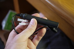
гӮ№гғҶгғғгғ—пјҷ
иҮӘи»ўи»ҠгҒёгҒ®еҸ–гӮҠд»ҳгҒ‘гҒҢз°ЎеҚҳгҒ«гҒҷгӮӢгҒҹгӮҒгҒ«гҖҒгғҸгғ–гғҖгӮӨгғҠгғўгҒёгҒ®гӮұгғјгғ–гғ«гҒ«гӮігғҚгӮҜгӮҝгғјгӮ’д»ҳгҒ‘гҒҫгҒ—гҒҹгҖӮз§ҒгҒҢе®ҹйҡӣгҒ«гҒ“гҒ®е……йӣ»еҷЁгӮ’дҪҝгҒҶгҒ®гҒҜе№ҙгҒ«2еӣһзЁӢеәҰгҒ§гҒҷгҒ®гҒ§гҖҒдҪҝгҒЈгҒҰгҒ„гҒӘгҒ„жҷӮгҒҜеҸ–гӮҠеӨ–гҒ—гҒҹгҒ„гҒ§гҒҷгҖӮгҒқгҒ®гҒҹгӮҒгҖҒз°ЎеҚҳгҒӘгӮігғҚгӮҜгӮҝгғјгӮ’д»ҳгҒ‘гҒҫгҒ—гҒҹгҖӮ
 гҖҖ
гҖҖ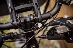
д»ҘдёҠгҒ§гҖҒ29gгҒЁгҒ„гҒҶи»ҪгҒ•гҒ®иҮӘи»ўи»Ҡз”ЁгҒ®USBе……йӣ»еҷЁгҒҢгҒ§гҒҚгҒҫгҒ—гҒҹгҖӮ
е®ҹйҡӣгҒ«дҪҝгҒЈгҒҰгҒҝгҒҰгғ»гғ»гғ»
д»ҠеӣһгҒ®иҮӘдҪңUSBе……йӣ»еҷЁгҒҜе®ҹгҒҜпј’еҸ°зӣ®гҒ§гҒҷпјҲеӣһи·ҜгӮ„йғЁе“ҒгҒҜе…ЁгҒҸеҗҢгҒҳпјүгҖӮ第дёҖеӣһзӣ®гҒ«гҒҜгҖҒе®№еҷЁгҒЁгҒ—гҒҰPVCгғ‘гӮӨгғ—гӮ’дҪҝгҒЈгҒҰгҒ„гҒҫгҒ—гҒҹгҖӮеӨ§еӨүеӨ§гҒҚгҒҸгҒҰгғҖгӮөгҒ„гҒ§гҒҷгҖӮгҒ—гҒӢгҒ—гҖҒеҠ№зҺҮжҖ§гҒӘгҒ©гҒ§гҒ„гҒҶгҒЁд»ҠеӣһгҒ®гғҗгғјгӮёгғ§гғігҒЁдёҖз·’гҒ§гҒҷгҖӮгӮҪгғӢгғјгҒ®ExperiaZгӮ№гғһгғӣгғігӮ’гҖҒиө°иЎҢпј‘пҪӢпҪҚгҒ”гҒЁгҒ«пј‘пј…е……йӣ»гҒ§гҒҚгҒҫгҒҷпјҲйӣ»жәҗOFFгҒ®зҠ¶ж…ӢпјүгҖӮExperiaZгҒ®гғҗгғғгғҶгғӘгғје®№йҮҸгҒҢеӨ§гҒҚгҒ„пјҲ2230mAhпјүгҒӘгҒ®гҒ§гҖҒгғҗгғғгғҶгғӘгғјгҒҢжҜ”ијғзҡ„гҒ«е°ҸгҒ•гҒ„iPhoneгҒ®гӮҲгҒҶгҒӘгӮ№гғһгғӣгғігҒӘгӮү1kmгҒ”гҒЁгҒ«пј’пј…зЁӢеәҰгҒ®е……йӣ»гҒҢгҒ§гҒҚгӮӢгҒӢгӮӮгҒ—гӮҢгҒҫгҒӣгӮ“гҖӮ
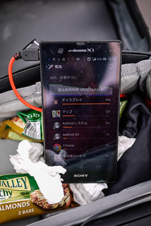
гҒ„гҒҡгӮҢгҒ«гҒ—гҒҰгӮӮгҖҒдёҖж—ҘгҒ®иҮӘи»ўи»Ҡгғ„гғјгғӘгғігӮ°гҒ§гӮ№гғһгғӣгғігҒ®гғҗгғғгғҶгғӘгғјгӮ’гҒ„гҒЈгҒұгҒ„гҒҫгҒ§е……йӣ»гҒ—гҒҰгҒҸгӮҢгҒҫгҒҷгҖӮжіЁж„ҸгҒ—гҒӘгҒҸгҒҰгҒҜгҒӘгӮүгҒӘгҒ„гҒ®гҒҜгҖҒгӮ№гғһгғӣгғігҒ®з”»йқўгҒ®йӣ»еҠӣгҒ®ж¶ҲиІ»гҒҢеӨ§еӨүеӨҡгҒ„гҒ§гҒҷгҒ®гҒ§гҖҒз”»йқўгҒҢгӮӘгғігҒ§гҒӢгҒӨGPSгӮ’дҪҝгҒҶGoogle MapsгҒӘгҒ©гҒ®гӮўгғ—гғӘгӮ’е®ҹиЎҢгҒ®гҒҫгҒҫгҒ§иө°иЎҢгҒҷгӮӢгҒЁгҖҒе……йӣ»еҷЁгӮ’жҢҮгҒ—гҒҰгӮӮгғҗгғғгғҶгғӘгғјгҒҜжёӣгҒЈгҒҰгҒ—гҒҫгҒ„гҒҫгҒҷпјҲе……йӣ»еҷЁгӮ’жҢҮгҒ—гҒҰгҒ„гҒӘгҒ„гӮҲгӮҠгӮӮж¶ҲиІ»гҒҢе°‘гҒӘгҒҸгҒӘгӮӢгҒ®гҒ§гҒҷгҒҢпјүгҖӮ
 гҖҖ
гҖҖ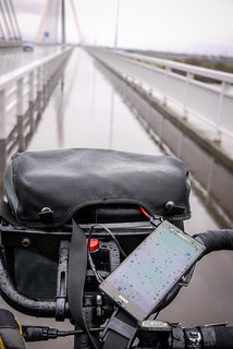
August 4th, 2013 | categorizilation: all categories,equipment,Hokkaido (Japan),Post-2008,Technology
In this post I describe how I made a USB smartphone charger for a hub-dynamo-equipped bicycle.В The idea came from multiple sources, includingВ Mr. Howdy, В Arenddeboer.com, andВ Peter. But they assume the person making the charger knows how to read a circuit diagram. I cannot understand a circuit diagram. If you’re like me, then this blog post is for you.
The rundown:
Total cost:В approx. US$15 (parts only; you need tools such as soldering iron etc.)
Weight: 29 grams
Weatherproof: Yes
Output: 5 volts DC (USB standard)
Input: 6 volts AC
Efficiency: Will charge a Sony Experia Z smartphone at a rate of approximately 1% per 1km (with the smartphone turned off).
Charge start:В 5.5km/h
What this device does
When charging your smartphone using a wall charger or your laptop’s USB, the electricity going into your phone is direct current (DC) at 5 volts. A bicycle dynamo hub, however, usually creates electricity in the form of alternating current (AC), at 6 volts. So, we’ve got to change the electricity created by the dynamo hub (6V AC) into the same type as what comes out of your smartphone wall charger or your laptop’s USB (5V DC). That’s what this device does.
Disclaimer:В I know nothing about electronics. This charger has worked well for me so far (about 1,000km of cycle touring), but it may turn on you and eat your smartphone’s innards alive, rendering it a useless shell. If you’d rather let someone else take the responsibility for your delicate electronics, check out the Bright-Bike Revolution (amazing value for a solid charger) or the Busch & MuellerВ Luxos IQ2 headlight with USB charging built in, or the Tout-Terrain Plug II.
What you need:
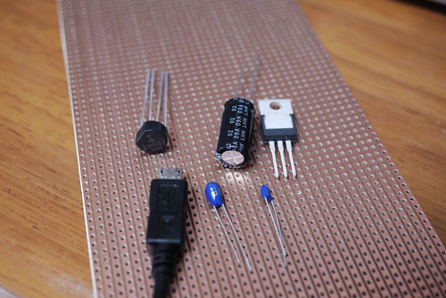
Step 1
Cut the veroboard (stripboard) into an oblong, 4 holes wide by approximately 25 holes long. I did this by scoring the board with a craft knife on both sides and then snapping it.
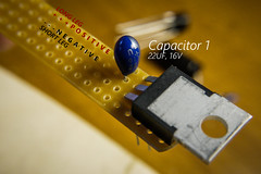
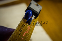
Step 2
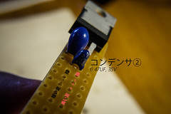
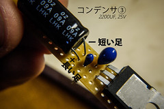
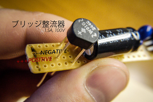
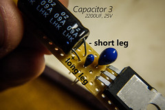
Start to populate your board. On the capacitors, the long leg is positive. Click on the photos for a larger version.
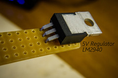
В Step 3
This step can be tricky…aligning the bridge rectifier in place. Note the polarity (positioning of the negative and positive legs).

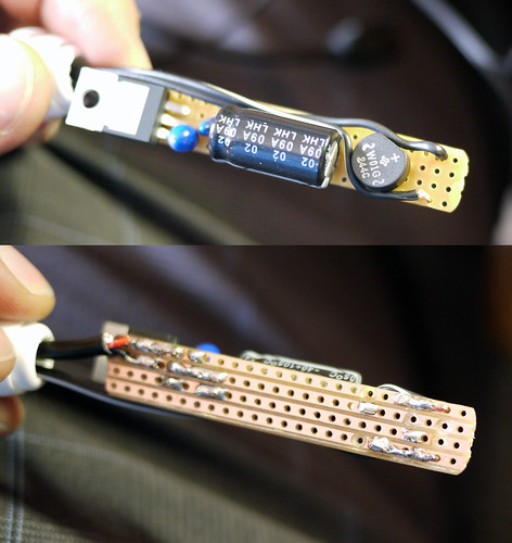
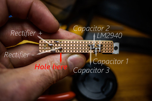
Looking from the top, your board should now look something like this.
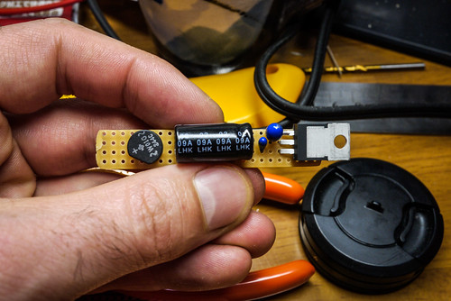
You can now go about carefully soldering the parts in place at the rear of the board. Take care not to overheat the parts, and make sure not to ‘connect’ any of the copper strips on the stripboard with stray bits of solder.
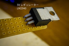
Post-soldering should look something like below. Ignore all the drill-marks, except for the one at the bottom. You need that one to stop current going directly to the regulator (LM2940). Holes can be made by hand-turning a 5mm drill bit.
Step 4
Prepare your micro-USB connector by butchering a cheap USB to micro-USB cable, discarding the big USB end. We will attach this to the circuit-board, and it will plug into your smartphone. Frustratingly, USB cable inner wire colors are sometimes different (like, green for negative). But most of the time, they will be red (positive), black (negative) and white (data). You won’t be needing the white wire, so you can cut it short.

Step 5
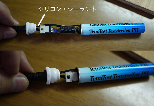
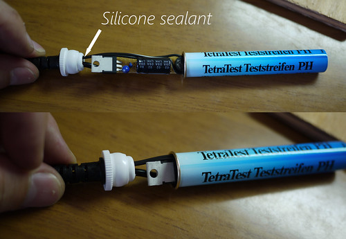
Before attaching the micro-USB cable to the circuit-board, a suitable case needs to be found. I happened to have an old fish-tank PH level tester container hanging around that was a perfect size.
Step 6
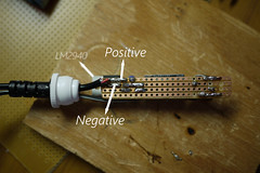
Container sorted, time to thread the cables through the openings and solder them to the circuit board. I first attached the micro-USB cable. Red on the positive line, black on the negative line.
Next, attach the wires that will run from the dynamo hub. The polarity (negative and positive direction) here doesn’t matter at all; the bridge rectifier has magic fairies inside that sort all that out.
Step 7
Install the circuit board in a suitable container. Before sealing the container up properly, now may be a good time to hook the unit up to a dynamo hub and smartphone to check that everything is working.
Step 8
This step is not essential, but I wanted to make this unit as weather-proof as possible. Using a couple of different size heat-shrink tubing, I covered the whole thing up, making it very weather-proof.
Step 9
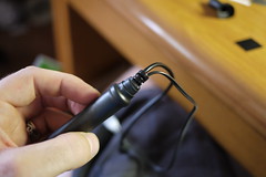
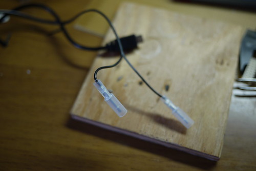
I wanted to be able to easily attach and remove the charger from my bike. The only time I use it is when I am cycle touring (about twice a year). This was easily done by using simple male/female connectors. The wire running from my hub to the female connectors is on my bike all the time, and I can just connect the charger when I need to.
So there you have it. A weather-sealed USB charger, powered by a bicycle dynamo hub. It weighs in at 29 grams. Just lovely.
Performance in the real world
This is the second charger I have made (using the exact same circuitry). The first one ended up in a PVC pipe casing, which is ugly and bulky. It works exactly the same as this new slick-cased version. Using the PVC-pipe-case version, I was able to get around 1% charge for every 1km pedaled on a laden, flat-terrain four-day cycle tour (with the phone powered off). That was charging a Sony Experia Z smartphone, which has a very large battery (2330пҪҚAh). With an iPhone, with its smaller 1440mAh, this might be more like 2% charge per 1km.
In any case, with the phone powered off, it will charge fully over a full day of cycling. It does not put out enough charge to keep up with intensive computing tasks like Google Map Navigation. That is, with the screen on all the time, plus the GPS running, the battery will still run down even while charging.
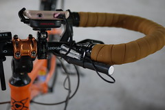
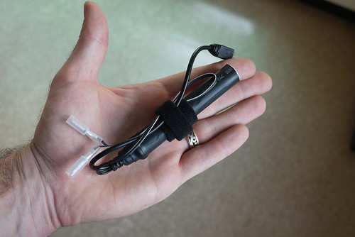
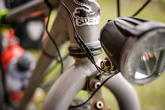
My wife has claimed this new version as her own, so I am still stuck with the PVC pipe version. On her bike, this is the set up we have at present (she doesn’t use a handlear bag). Here, the charger is attached using a cable tie, in the photo at the top of this post, we have attached a velcro strap, which will make attaching/removing the charger easier.