
August 4th, 2013 | categorizilation: all categories,equipment,Hokkaido (Japan),Post-2008,Technology
In this post I describe how I made a USB smartphone charger for a hub-dynamo-equipped bicycle.┬ĀThe idea came from multiple sources, including┬ĀMr. Howdy, ┬ĀArenddeboer.com, and┬ĀPeter. But they assume the person making the charger knows how to read a circuit diagram. I cannot understand a circuit diagram. If you’re like me, then this blog post is for you.
The rundown:
Total cost:┬Āapprox. US$15 (parts only; you need tools such as soldering iron etc.)
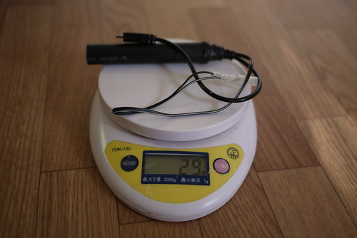
Weight: 29 grams
Weatherproof: Yes
Output: 5 volts DC (USB standard)
Input: 6 volts AC
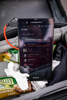
Efficiency: Will charge a Sony Experia Z smartphone at a rate of approximately 1% per 1km (with the smartphone turned off).
Charge start:┬Ā 5.5km/h
What this device does
When charging your smartphone using a wall charger or your laptop’s USB, the electricity going into your phone is direct current (DC) at 5 volts. A bicycle dynamo hub, however, usually creates electricity in the form of alternating current (AC), at 6 volts. So, we’ve got to change the electricity created by the dynamo hub (6V AC) into the same type as what comes out of your smartphone wall charger or your laptop’s USB (5V DC). That’s what this device does.
Disclaimer:┬ĀI know nothing about electronics. This charger has worked well for me so far (about 1,000km of cycle touring), but it may turn on you and eat your smartphone’s innards alive, rendering it a useless shell. If you’d rather let someone else take the responsibility for your delicate electronics, check out the Bright-Bike Revolution (amazing value for a solid charger) or the Busch & Mueller┬ĀLuxos IQ2 headlight with USB charging built in, or the Tout-Terrain Plug II.
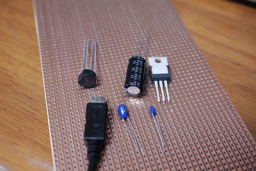
What you need:
Step 1
Cut the veroboard (stripboard) into an oblong, 4 holes wide by approximately 25 holes long. I did this by scoring the board with a craft knife on both sides and then snapping it.
Step 2
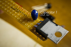
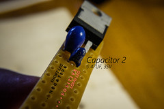
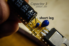
Start to populate your board. On the capacitors, the long leg is positive. Click on the photos for a larger version.
┬ĀStep 3
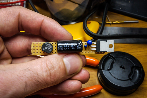
This step can be tricky…aligning the bridge rectifier in place. Note the polarity (positioning of the negative and positive legs).

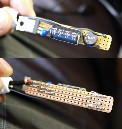
Looking from the top, your board should now look something like this.
You can now go about carefully soldering the parts in place at the rear of the board. Take care not to overheat the parts, and make sure not to ‘connect’ any of the copper strips on the stripboard with stray bits of solder.
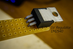
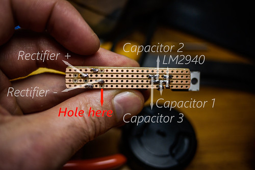
Post-soldering should look something like below. Ignore all the drill-marks, except for the one at the bottom. You need that one to stop current going directly to the regulator (LM2940). Holes can be made by hand-turning a 5mm drill bit.
Step 4
Prepare your micro-USB connector by butchering a cheap USB to micro-USB cable, discarding the big USB end. We will attach this to the circuit-board, and it will plug into your smartphone. Frustratingly, USB cable inner wire colors are sometimes different (like, green for negative). But most of the time, they will be red (positive), black (negative) and white (data). You won’t be needing the white wire, so you can cut it short.

Step 5
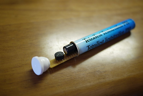
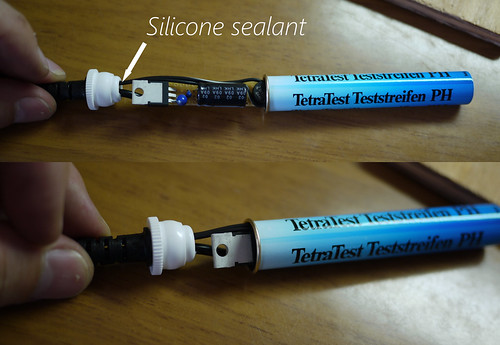
Before attaching the micro-USB cable to the circuit-board, a suitable case needs to be found. I happened to have an old fish-tank PH level tester container hanging around that was a perfect size.
Step 6
Container sorted, time to thread the cables through the openings and solder them to the circuit board. I first attached the micro-USB cable. Red on the positive line, black on the negative line.
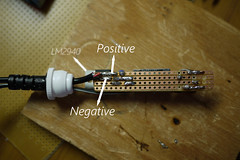
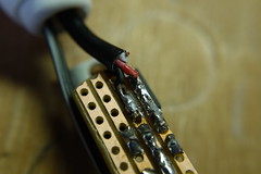
Next, attach the wires that will run from the dynamo hub. The polarity (negative and positive direction) here doesn’t matter at all; the bridge rectifier has magic fairies inside that sort all that out.
Step 7
Install the circuit board in a suitable container. Before sealing the container up properly, now may be a good time to hook the unit up to a dynamo hub and smartphone to check that everything is working.
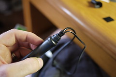
Step 8
This step is not essential, but I wanted to make this unit as weather-proof as possible. Using a couple of different size heat-shrink tubing, I covered the whole thing up, making it very weather-proof.
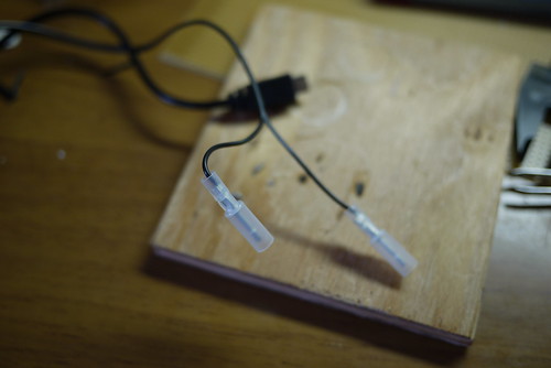
Step 9
I wanted to be able to easily attach and remove the charger from my bike. The only time I use it is when I am cycle touring (about twice a year). This was easily done by using simple male/female connectors. The wire running from my hub to the female connectors is on my bike all the time, and I can just connect the charger when I need to.
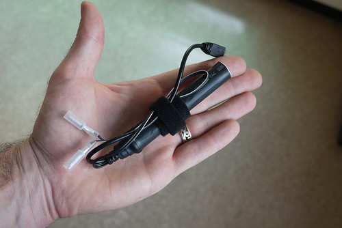
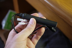
So there you have it. A weather-sealed USB charger, powered by a bicycle dynamo hub. It weighs in at 29 grams. Just lovely.
Performance in the real world
This is the second charger I have made (using the exact same circuitry). The first one ended up in a PVC pipe casing, which is ugly and bulky. It works exactly the same as this new slick-cased version. Using the PVC-pipe-case version, I was able to get around 1% charge for every 1km pedaled on a laden, flat-terrain four-day cycle tour (with the phone powered off). That was charging a Sony Experia Z smartphone, which has a very large battery (2330’ĮŹAh). With an iPhone, with its smaller 1440mAh, this might be more like 2% charge per 1km.
In any case, with the phone powered off, it will charge fully over a full day of cycling. It does not put out enough charge to keep up with intensive computing tasks like Google Map Navigation. That is, with the screen on all the time, plus the GPS running, the battery will still run down even while charging.
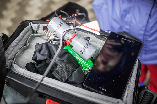
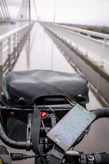
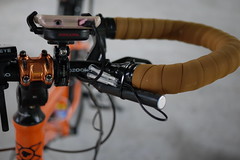
My wife has claimed this new version as her own, so I am still stuck with the PVC pipe version. On her bike, this is the set up we have at present (she doesn’t use a handlear bag). Here, the charger is attached using a cable tie, in the photo at the top of this post, we have attached a velcro strap, which will make attaching/removing the charger easier.

This is an amazing guide. Clearest I’ve seen yet for those of us with no electronics background. I’m going to have a go at this.
Am I right in thinking the stripboard is standard pitch (0.1 inch), so the board you cut off is less than half an inch wide?
And, other than for size, is there any reason why C3 isn’t a capacitor rated higher than 25v?
Finally, did you need a special soldering iron with a fine tip?
Thanks!
can be possible to put a Dynamo of 12V 3W instead input of 6V 3W with this same arragement to get 5V output?
sorry I meant Dynamo of 12V 6W in my previous Comment,…
I’m using a 6V AC – 3W dynohub
and it works fine for my old HTC smartphone.
gives perfect 5V and charges my phone.
So I tried it out with my Samsung Galaxy S3. The charging connects, so my phone thinks it’s charging, but in reality it is not. It is still using energy and won’t charge at all.
I’ve read a lot about this problem for iJunk (as i like to call it) and they need a voltage reference on the data lines for it to charge at different speeds. All i can find about this for a galaxy is shorting the data lines instead of leaving them to float. Now shorting the data lines will tell the phone it is plugged into the wall and can take as much power as it wants. So i’m afraid that if I do this it might blow the 7805 or another part of the circuit.
Or is my smartphone smart enough to take the max amount of current available? (while watching the Vcc usb so it doesn’t fall under lowest limit.)
Or what should the voltage reference be for my phone so it takes 500mA
Hi! Thanks for schematics. I installed USB A-socket directly to the veroboard. It’s working now. I checked quickly today. Better test will be done after I build my new wheel with better parts.
Hi all,
After your test, can you tell me which components i need (I have galaxy II).
Thanks.
Sharon
